


Ultimate Resolution of Atomic Force Microscopy
To image surfaces in atomic force microscopy (AFM), a cantilever with a nanometer-sharp tip scans the surface. Depending on the imaging mode, the tip-sample interaction forces either introduce a static deflection of the cantilever or, for dynamic AFM modes, change the frequency, amplitude or phase of the cantilever oscillation. Contact and Tapping mode AFM operate in a repulsive tip-sample force regime, where the tip is in contact or intermittent contact with the surface. This can lead to tip wear and sample damage. In Park’s True Non-contact mode on the other hand, the tip oscillates in close proximity of the surface in the attractive force regime, without tip-sample contact, thus facilitating non-invasive and highly accurate topography imaging. Park’s XE-series were the first AFMs in the market to realize a straightforward, simple-to-use Non-contact mode in every specification. True Non-contact mode achieves an unprecedented control of tip-sample distance at the subnanometer scale, combined with superb tip and sample preservation. This is due to the fast response of Park’s decoupled Z and XY scanners, which allow a precise tracking of the cantilever oscillation. The fast Z feedback facilitates a prompt retraction of the cantilever when the tip encounters topographic features and keeps tip-sample interaction in the attractive force regime.
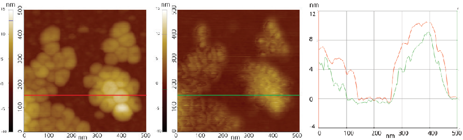
(a) Height image of F14H20 by Non-contact mode (b) Height image of F14H20 by Tapping mode (c) Line profile comparison
By avoiding tip wear, True Non-contact mode offers the ultimate resolution for ambient AFM, far surpassing the capabilities of both Contact and Tapping mode. Moreover, due to its non-invasive nature, True Non-contact mode can image soft samples (e.g. biological samples and soft polymers) without sample damage, figure 1(a), as commonly observed when using Contact or Tapping mode, figure 1(b).
True Non-contact mode is a dynamic AFM technique, where the cantilever oscillates at its resonance frequency in close proximity of the surface of a sample. The tip-sample distance is on the order of tens to hundreds of angstroms in the non-contact regime of the LennardJones potential in figure 2, which is used as approximation for the tip-sample interaction. For small tip-sample distances below 10 nm, two major interatomic forces act between tip and sample: a short-range repulsive force and a longer-range attractive force. The repulsive interaction force (Frep) is a direct consequence of the Pauli exclusion principle that forbids the overlap of electron clouds, while the attractive interaction force, the so-called van der Waals force (FvdW) originates from dipoledipole interactions between the atoms of tip and sample. As the distance between tip and sample decreases, the short-range repulsive force dominates the interaction and the magnitude of the force gradient increases significantly. Therefore, techniques like Contact or Tapping mode, that operate at small tipsample distances in contact or intermittent contact, measure topography based on this short-range repulsive force at the expense of tip and sample integrity. However, as the distance between tip and sample increases, the attractive van der Waals force begins to govern the interaction. Park’s True Non-contact mode measures surface topography based on this attractive interatomic force and thereby prevents tip or sample damage.
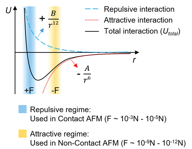
Figure 2. Interatomic interaction potential U vs. distance r as approximation for the tip-sample interaction. The blue curve represents a purely repulsive interaction, while the red curve represents a purely attractive interaction. The black curve is a combination of long-range attractive and short-range repulsive interaction called the Lennard-Jones Potential. At larger distances, the net force is attractive (-F), which switches to a net repulsive force (+F) when two atoms are brought closer.
For the oscillation in True Non-contact mode, the cantilever is driven at its resonance frequency (f0). The resonance frequency of a cantilever is given by its intrinsic spring constant (k0) and mass (m), as shown in equation (1). When the cantilever approaches the sample surface, the resonance frequency shifts due to the attractive van der Waals force acting between the atoms of the tip apex and the sample surface. This shift of the resonance originates from a change of the spring constant from the initial intrinsic value k0 to an effective spring constant (keff), as given by the following equations:
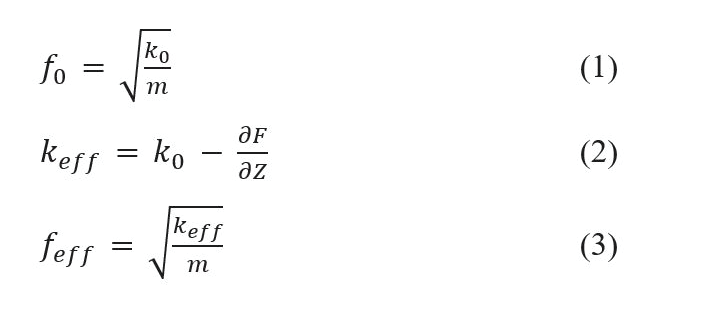
In the attractive van der Waals force regime at larger tip-sample distances, keff becomes smaller than k0 since the force gradient F' (=∂F/∂z) is positive, in agreement with equation (2) and (3). To detect the changes of the effective spring constant and therefore resonance frequency, True Non-contact mode monitors the amplitude of cantilever oscillation. The detection of amplitude changes is more sensitive to the tip-sample distance than changes of the static cantilever deflection and is used for Tapping mode, Electrostatic force microscopy (EFM) and Magnetic force microscopy (MFM) as well.
To introduce the mechanical oscillation of the cantilever a piezo-element with a wide range of frequencies drives the cantilever. The cantilever’s resonance frequency f0 is identified by sweeping the frequency of the drive piezo over certain range with a distinct peak at the resonance. Figure 3 displays the relation between the cantilever’s amplitude and the drive frequency at resonance without interaction forces (a) and in the attractive force regime, used for Park’s True non-contact mode (b).
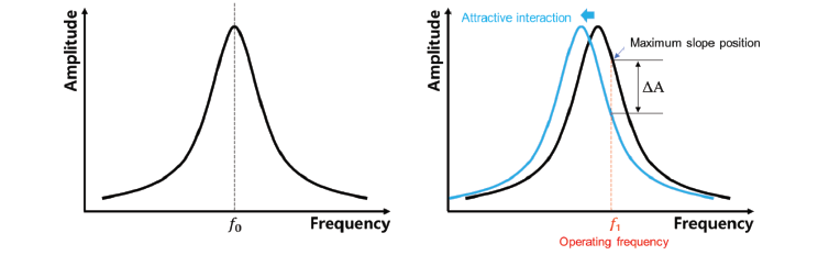
Figure 3. Schematic of cantilever resonance (a) without tip-sample interaction and (b) for Park’s True Noncontact mode operated in the attractive force regime, leading to shift to lower frequencies in blue. The detected change in the oscillation amplitude at the operating r drive frequency f1 is indicated as ∆A.
For True Non-contact mode the operating or drive frequency f1 is slightly larger than f0 , see figure 3(b). As shown in equations (2) and (3), keff decreases with respect to k0 due to the attractive force, leading to a shift of the resonance to lower frequencies and a negative change in the oscillation amplitude ∆A measured at f1 . At f1 the slope of the curve reaches its maximum, which leads to a large amplitude change ∆A even at small changes of the resonance. Therefore, the amplitude change measured at f1 is highly sensitive to changes in the tip-sample distance (∆d).
As variations in sample topography will introduce changes in the tip-sample distance ∆d and interaction forces, the amplitude change ∆A can detect the sample topography. Therefore, True Non-contact mode uses the oscillation amplitude measured at the operating frequency f1 as feedback signal.
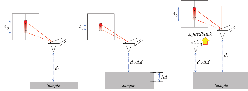
Figure 4. Tip-sample distance dependence of the oscillation amplitude and the Z feedback
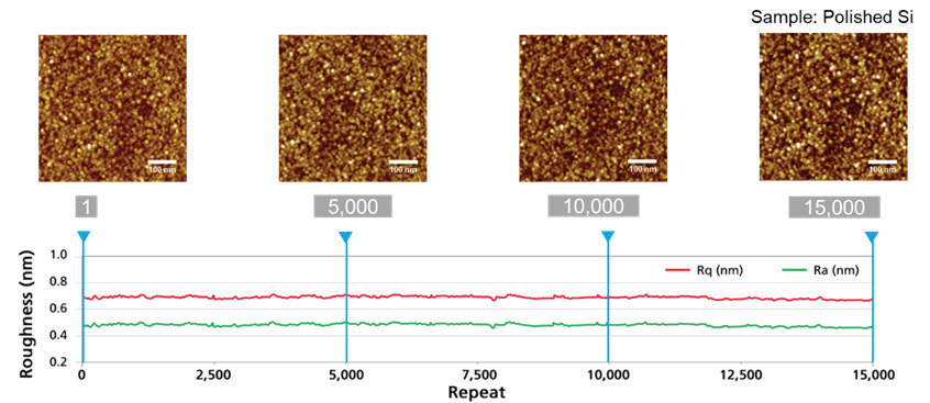
Figure 5. Long-term Non-contact mode repeat measurements without tip damage. 15,000 repeat measurements on polished Si substrate with 3Hz scan rate.
The feedback controls the movement of the Z scanner during imaging to compensate for deviations of the amplitude from the predefined setpoint (the reference amplitude for feedback) and thereby distance changes between the tip and the sample as shown in figure 4. By maintaining a constant amplitude and distance, True Non-contact mode reconstructs the sample topography from the Z scanner movement. Since the attractive force regime (figure 2) is quite narrow, the Z feedback to regulate the tip-sample distance needs to be sufficiently fast to react to any kind of changes in the topography to avoid tip-sample contact.
Typically, in long-term Contact or Tapping mode measurements, the tip apex suffers from wear as the scanning proceeds. The tip wear increases the tip radius, which lowers the spatial resolution and accuracy of roughness measurements. Figure 5 shows four True Non-contact mode images out of a measurement series with 15,000 scans taken with the same cantilever, and a corresponding plot of the surface roughness over the scan number. Different from other AFM topography modes, the spatial resolution and the surface roughness stays constant over the whole measurement series. The repeatability and precision of Park’s True Non-contact mode is owed to the highly accurate feedback system and the Z scanner stability, allowing continuous Non-contact imaging over 72 hours without adjusting any scan parameters.